How it Works
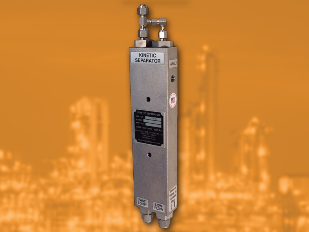
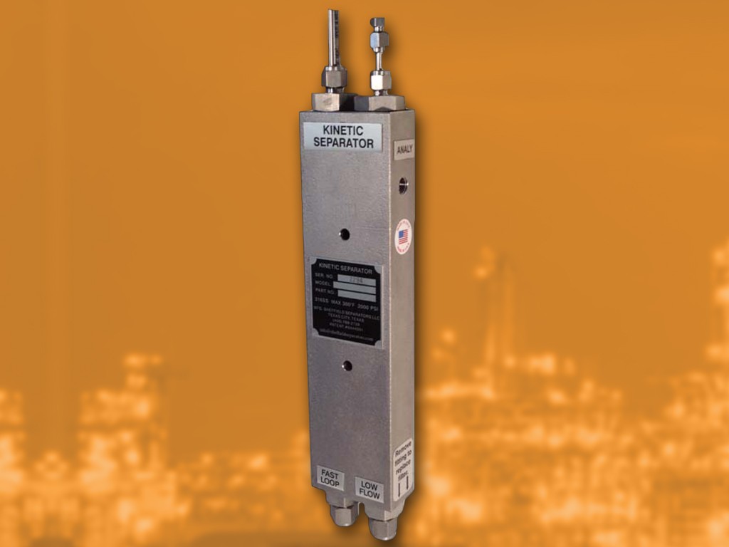
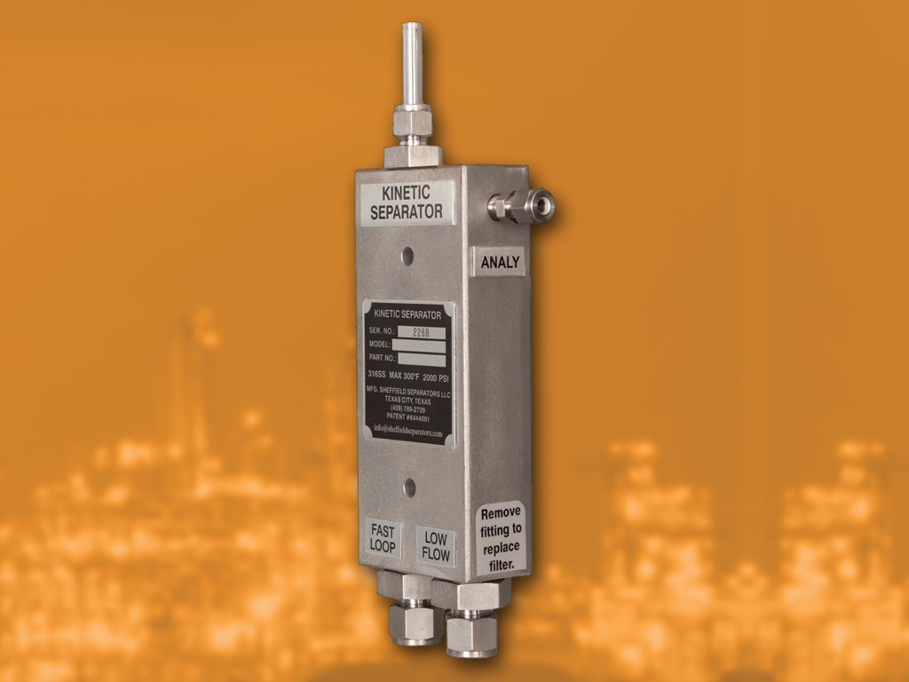
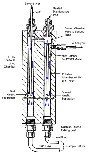
- Sheffield Dual Chamber Kinetic Separators use patented technology to take advantage of kinetic energy to separate the desired analyzer sample from impurities often found in a process stream. This is accomplished by establishing fast loop flow from a high pressure sample tap to a low pressure sample return. Reversing the flow of a relatively small slipstream sample creates kinetic energy separation. Condensate and particulates in gas samples and any heavy immiscible liquid phase and solid contaminants in liquid samples will not negotiate this reversal of flow direction. Particulates, condensables, and heavy immiscible liquids are separated from the analyzer feed stream. To further effect this separation, a second kinetic chamber with a hydrophobic filter polishes the sample. Although kinetic energy will physically separate impurities, it will not alter the chemical composition of the sample.
Superior Technology
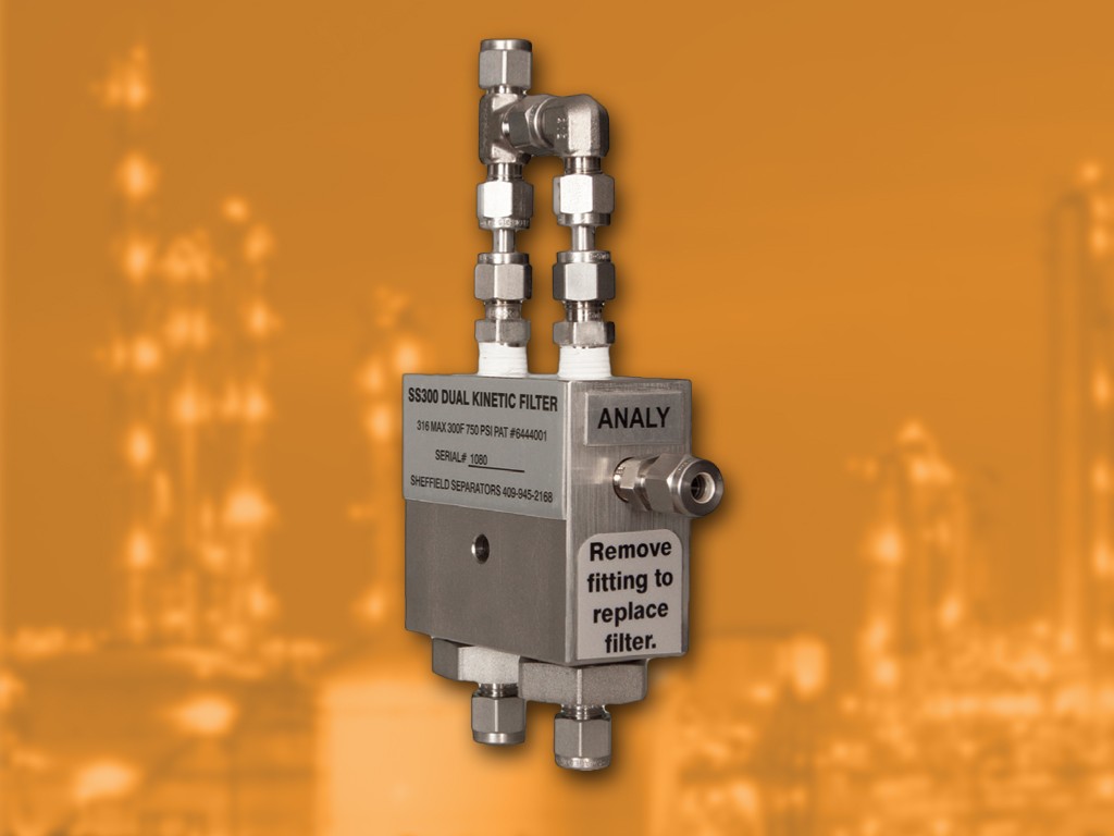
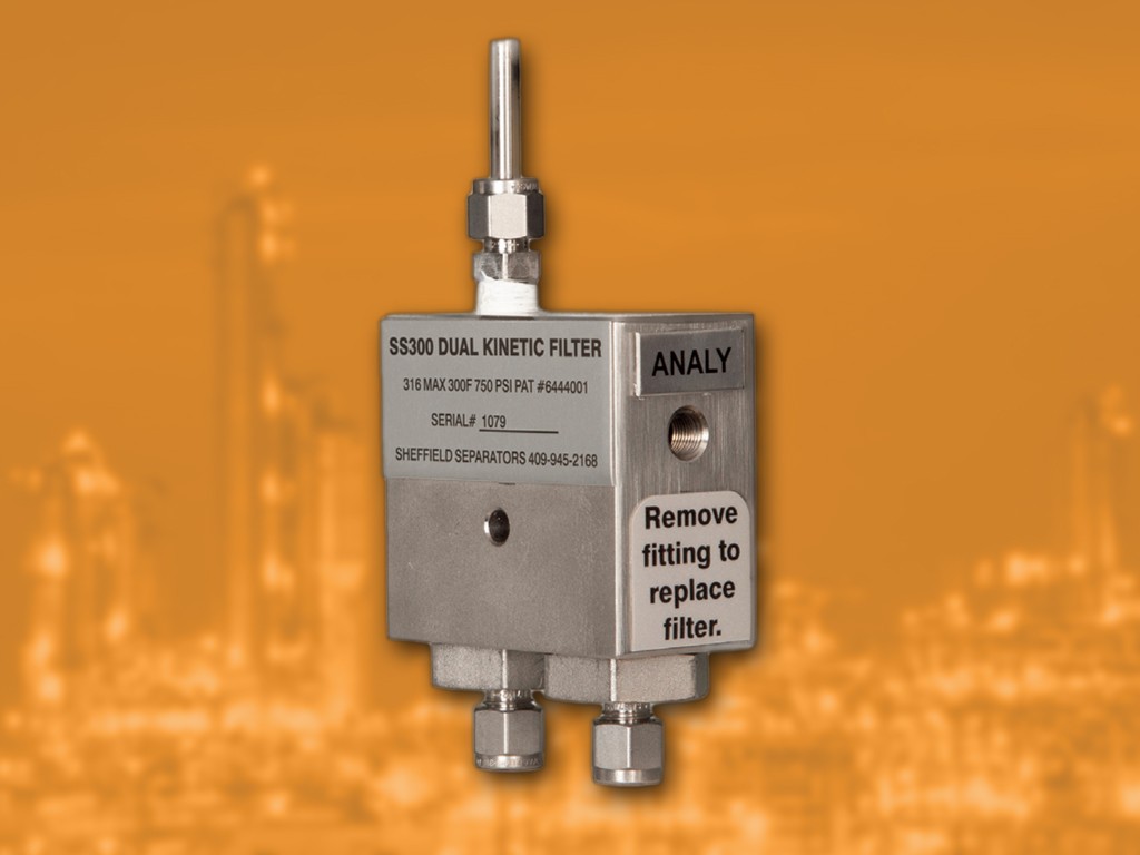
- Unlike older technology represented by knock-out and centrifugal separation or membrane filters, Sheffield Separators use a combination of kinetic separation and hydrophobic filters to clean and polish samples. Sheffield provides a product for most applications: gas, liquid hydrocarbon, or other liquids and for varying degrees of contamination. Sheffield recently added addition of Lab Sample Conditioning System Panels to our product offerings. These panels will feature the patented Sheffield Dual Chamber Kinetic Separator and are designed to clean and condition laboratory samples either at the collection point in the field or in the laboratory. Also, we are pleased to announce an optional cooler available with its SS1200 and SS700 models which will virtually eliminate condensables from the product stream. The SS300 models are recommended as a replacement for standard 2.25” filters commonly used in analyzer sample systems. The SS300 models are designed and built for routine use, but offer twice the filtration of older standard filters and provide kinetic energy separation to remove condensables without increasing lag time.
- Analyzers are sensitive sophisticated equipment which will not function at the highest level if exposed to particulate or condensables. Expensive analytic equipment can be permanently degraded by using outdated and inadequate protection. Kinetic separation when combined with hydrophobic filtration will virtually eliminate analyzer fouling. A variety of filters, including back-flush and extremely hydrophobic filters are available to target specific contaminants.
Superior Results
Sample conditioning should result in delivering a sample that is representative of the process without compromising the integrity of the sample or the analyzer. The sample should represent as closely as possible the characteristics of the process material. Sheffield Dual Chamber Kinetic Energy Separators utilize the patented, superior technology of kinetic separation to physically separate impurities from the sample stream without altering the chemical composition of the sample, resulting in superior analyzer performance, lower maintenance, and more accurate sample readings than any other technology on the market today.
- Longer Analyzer Life
- Easy installation
- Easy filter removal
- Longer filter life
- Broad range of temperature, flow, and pressure
- Low Maintenance
- Not Affected by Unit Upset Conditions
- Cleaner slip stream
Superior Quality
Sheffield Separators are constructed with no moving parts for low maintenance and durability. All parts are 316 Stainless Steel, PTFE Teflon, O-rings, or filter material. Very durable materials and superior design assure that there will be no wear and the products will last for many years. Normal maintenance is one filter per year.
Superior Service
The Sheffield Dual Chamber Kinetic Energy Separator was invented by Glenn Sheffield as a practical solution to analyzer fouling problems caused by inadequate sample conditioning – more about us. New products have been developed based on the needs of customers and tested in real-time under actual field conditions. Standard Sheffield products may be special ordered with different filter configurations or different materials to suit unique application requirements. Sheffield customers have access to expert advice and practical tips to keep their analyzers functioning at optimal levels. View our technical articles. Use the form below to contact us and discuss your sample conditioning needs and see how the Sheffield Separator can reduce your maintenance and improve the performance of your analyzer.